Initial Configuration for Torchmate Driver Software Version 3
Motor Setup
For all Torchmate CNC systems the motion of the table is controlled by the motor drive box whether servo or stepper motors are being used the signal generator sends signals to specific axis lines. The number of motors used and the speed that the motors can travel depends on the type of table. For tables that use one motor for each axis, the motor cables should be attached to the ports labeled Axis 1 and Axis 2 on the back of the motor drive box. For tables that use two motors along the long axis and another for the gantry axis the port labeled Axis 3 should also be used; likewise if a router is connected either Axis 3 or Axis 4 would be used depending on how many other motors are connected. It is not critical as to what port each motor is plugged into as the first step is configuring the motors to move in the proper direction. To enable a motor line go to Configuration > System > Motor Signals in this menu each axis port is listed with the axis it is controlling.

The first step is to visually determine where each direction of travel should be on the table. When a drawing is created it will reference a vertical (Y) direction and a horizontal (X) direction, the drawing will translate into motion on the table in those directions. The first configuration step is to determine if the table’s motor signals result in the motion desired.
Begin in the driver software by going to the menu along the bottom and select Jog.
By pressing and holding one of the four direction buttons the table will move in that direction. Physically on the table determine what direction of travel should be ‘up and down’ and what direction should be ‘left and right’. More than likely the direction the table actually moves when using the Jog buttons will not match the direction desired.
If using a ‘Z’ axis (for routing not an arc voltage height control) there will need to be additional changes to enable the axis. Go to Configuration > Machine > Mechanics. For the Z axis the Gear Ratio needs to be changed to 1.0 and the Screw Thread changed to 20.0, also to enable the axis check Z under the Use Axis option.
To change the direction the motors travel go to Configuration > System > Motor Signals.
The Controller Axes section lists each port on the motor drive box. If the table uses more than two motors set port 3 and 4 to the motors being used. Make any appropriate axis changes then select OK and test in the Jog menu to see if the motors move properly. In most cases a few tests and changes will be necessary. If the motor moves along the correct axis but not in the correct direction adjust the Motor Direction to the opposite polarity to reverse the motion. The goal of this configuration change is to orient the motion of the table to the motion desired
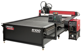
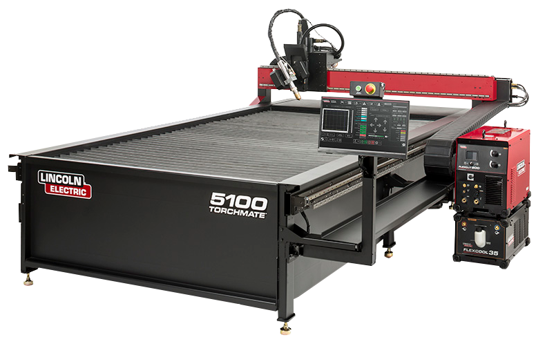
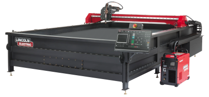
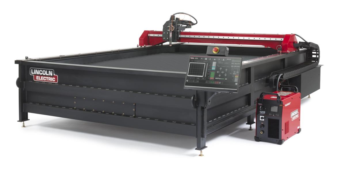
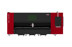
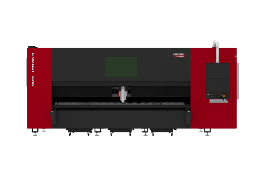
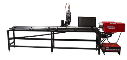
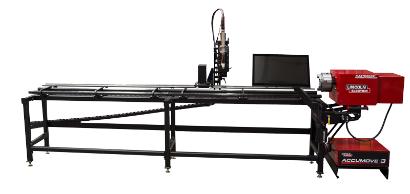
Torchmate uses three types of drive systems. If a system consists of a motor drive box and signal generator separate from each other it is either a stepper or servo system. A stepper system will have a black motor drive box. Servo motors will use a silver motor drive box. If the system consists of a single electronics unit in a red and black case it is a micro stepping system.
For stepper systems select Torchmate 2A Half Stepper (5000-0xx-1xxxxx)
For servo systems select Torchmate 8A Servo (FCS-x182D)
For micro stepping systems select Torchmate 3.5A Micro Stepper (5000-0xx-3xxxxx). This will change the values under the pull down. Then select Other from the same pull down. This will allow the fields below to be changed. Change the Step Pulse Width to 2 msec.
Additionally for micro stepping systems go to Configuration > Machine > Mechanics. Change the Step Mode to 10 micro steps / full step.
A few things to keep in mind when adjusting the motor signals:
-
The axis defined as ‘X’ and ‘Y’ can be defined based on the orientation of the table. The goal is to be able to visualize the plate and motion of the table as a drawing is being made so that a drawing translates correctly.
-
When using two motors along a single axis be sure that the ‘Motor Direction’ for the two motors are opposite of each other as they need to spin in opposite directions to move the gantry in the same direction.
The next step is to adjust the settings of the motors to improve accuracy and performance in Configuration > Machine > Feedrate/Ramping.
The Axis Settings determine the performance of the table. For all tables the settings for X and Y will be identical to each other. The Z axis settings will be unique, and A will not be utilized by any Torchmate system though in some special applications a rotary axis may be used. Depending on the type of motor being used the ideal settings will be different.
Stepper & Micro Stepping Motors:
|
Axis |
Start/Stop Feedrate |
Maximum Feedrate |
Ramping Rate |
Direction Change Delay |
Continuous Contouring Feedrate |
||
|
X |
35 |
250 |
10 |
.001 |
70 |
||
|
Y |
35 |
250 |
10 |
.001 |
70 |
||
|
Z |
5 |
15 |
1 |
.001 |
10 |
||
|
Max Arc Feedrate |
100 |
||||||
Servo Motors:
|
Axis |
Start/Stop Feedrate |
Maximum Feedrate |
Ramping Rate |
Direction Change Delay |
Continuous Contouring Feedrate |
||
|
X |
35 |
1000 |
10 |
.001 |
70 |
||
|
Y |
35 |
1000 |
10 |
.001 |
70 |
||
|
Z |
5 |
50 |
1 |
.001 |
10 |
||
|
Max Arc Feedrate |
100 |
||||||
Jog Settings
In the Jog menu to the right of the direction buttons there is an option to use three preset speeds. These speeds can be adjusted to allow for precise positioning using the Slow speed and a sufficient speed using Fast to move the gantry across the table. To change these settings go to Configuration > Preferences > Jogging.
Stepper & Micro Stepping Motors:
|
Axis |
Slow |
Medium |
Fast |
|
X |
10 |
100 |
175 |
|
Y |
10 |
100 |
175 |
|
Z |
2 |
7 |
12 |
Servo Motors:
|
Axis |
Slow |
Medium |
Fast |
|
X |
10 |
250 |
700 |
|
Y |
10 |
250 |
700 |
|
Z |
2 |
20 |
40 |
The Initial Jog Rate adjusts which speed setting will be defaulted to when the Jog menu is accessed.
Gear Ratio Testing:
Each axis has a default gear ratio that is set for Torchmate’s standard gear and pulley system. This number can be adjusted to fine tune for unique conditions of a table. To test that the gear ratio is set correctly go to the Point along the bottom of the driver software. Adjustment is only necessary if the table is not moving the correct distance when told to.
The point menu allows a certain distance to be moved at a prescribed speed. To move a certain distance set the first pull down to Incremental then specify a distance to travel along an axis and select move. The table will move at the speed listed under Feedrate, this can be any specified speed or in the pull down menu Rapid can be selected, this is the speed at which the table will travel between cuts.
To test the gear ratios start with the gantry near one edge of the table, one axis will be tested at a time. Measure the position of the gantry in reference to a fixed position on the table, this point will be used to determine how far the table actually moves. Input a distance for the table to move and press Move. Measure the distance that the table physically moves; the farther the table moves the more accurate the gear ratio adjustment will be, starting from one limit of travel and moving at least half the total table dimensions would be ideal. Repeat the measurements for each the other axis, gear ratio testing is only necessary on X and Y axes. Once both distances are measured use the following formulae to calculate a new gear ratio.

To access the gear ratio settings go to Configuration > Machine > Mechanics.