Poor Circular Cutting in Version 2 of the Torchmate Driver Software
Poor Circular Cutting
There are three basic reasons for poor circular cutting, the design of the image, the mechanical operation of the gantry, and the plasma cutter’s configurations. We will discuss all three of these topics.
The Imported DXF file
It is crucial that the imported DXF image files be as close to the tolerances you are trying to achieve, so that when converted into G-code the information is written exactly as it was drawn. Since these images are made up by nodes, it may be necessary for you to manually change these nodes into a format that will provide circular movement as opposed to right angle movement.
While in the Torchmate CAD, create your circular shape. Once the image is on the material sheet, double left click on the line of the image to expose the nodes that make up the shape. To provide the best contour for a circular shape, the exposed nodes should appear as “round” looking nodes. This type of node is called a Curve Node, and it promotes curved paths. If your nodes look like “Plus signs” (+ Corner nodes), or like Triangles (Tangent node), you may want to change the characteristics to get a better image of what you are trying to cut. You can do this with the aide of the Edit Toolbox, a tool that can only be utilized while the nodes are exposed. Select a single node, or a group of nodes you wish to change with your Select tool, then by holding the right mouse key down, drag the mouse in the direction of the type of node you wish to change it in to (upper left for Corner node, Upper right for Curve node, lower right for Tangent node). This action will change the node’s characteristics, and in so doing, allow the contour of your shape to be much smoother or rounder than before. This should help the DXF file be converted in to a G-code file with the same dimensions as those drawn.
It is also important that the DXF file have all of its lines recognized as being connected. If you have imported a file from software like AutoCAD, you may want to increase your Join tolerance in the Import Configuration page to 0.01, as this will allow any gap smaller than .01 to be closed by the driver software at import. Below is an example of the Import configuration window, with the change highlighted in Blue.
The Mechanical Operation
Another problem that can cause the circular cutting to be less than perfect is in the mechanical operation of the table and gantry. For the motors to be in tune with the Signal Generator and PC, it may be necessary for you to test the X and Y axis to be certain that they are moving exactly as the driver software thinks it is moving the table. You can download a copy of the “Testing your X & Y Axis” Adobe acrobat file on the Torchmate Customer Tech Support website, to help you with this testing. Basically we will mark the spot of where the torch is resting, and then move the axis motors in specified distance on the X or Y axis, and then marking the final resting position. By physically measuring the distance between the two points, we can compare that against the distance we had programmed the table to travel, and this will help us to know if the table is running true with the software, or not. Using this information, we can recalculate the Gear Ratio to “Dial in” the proper settings.
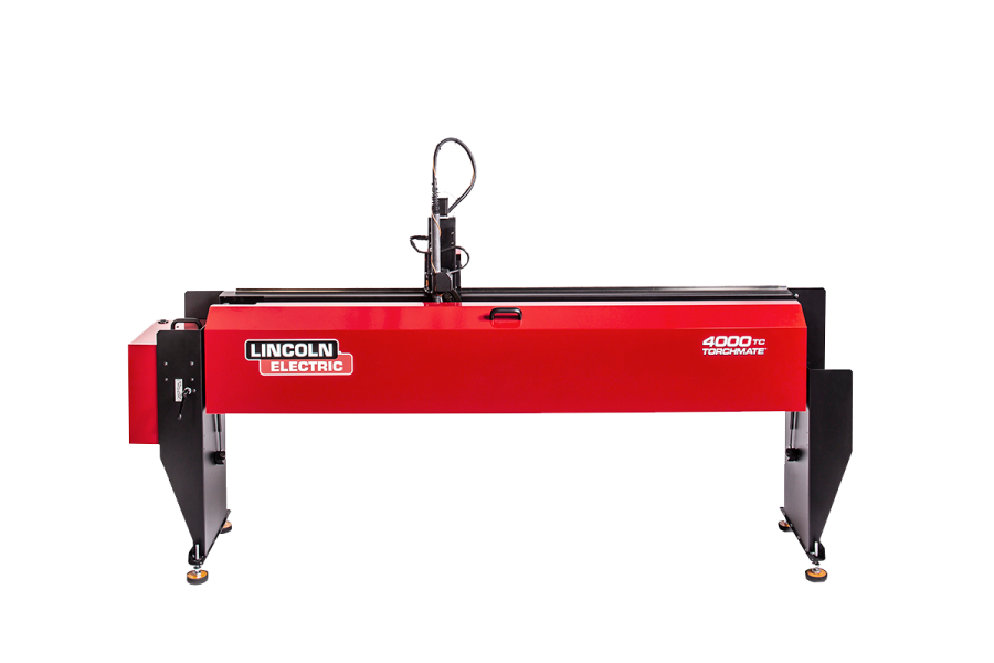
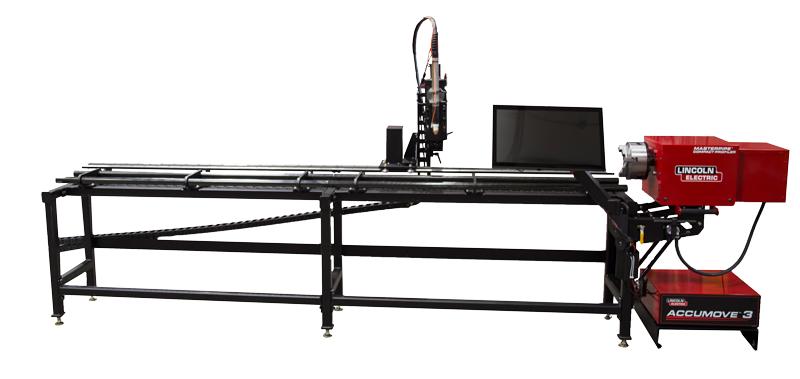
Another issue that must be addressed is in the mechanisms that actually move. Be sure to check all of the set screws on the motor pulleys, the tension of the belts, and the interaction of the spur gear and the gear track. If any of these components are loose, or show signs of excessive wear, take the time to inspect and make any adjustments necessary. A drop of “Loc-Tight” on the set screw threads can help to prevent these screws from backing out. It is also recommended that at lest one of the set screws be positioned on the flat portion of the motor spindle, as this can help to resist slippage. The belt tension should be enough to keep the spur gear in place, but also to prevent any slipping on the pulleys as well. The Spur Gear should move easily in the gear track, but not be so loose that it is not meshing with the gear track in a proper way. If it is too tight, it may cause too much resistance, thus the motors can slip and lose position. A periodic check of these mechanisms will help to ensure that your table will not lose position because of mechanical failure.
Driver Software Configuration
Please take the time to read through the Owner’s Manual for your Plasma torch. In most cases, a Cut Chart with recommended settings is posted inside. These settings are based on the type of material and the thickness you are cutting, and will provide you with the proper amount of Amps, Volts, Air Pressure, and Feedrate, to name a few. Improper settings can result in poor cutting results, or partial tool path cutting.
On the Torchmate Customer Tech Support website, there is a file titled “Configuration”, which will present the correct configuration settings for all pages in the Configuration menu of your driver software. It is especially important to make adjustments to the Feedrate/Ramping page for the Start/Stop Feedrate, and the Maximum Feedrate. The Start/Stop Feedrate is the initial take-off speed for the motors from a resting position. To help prevent against quick or “jerky” movements, you will want to lower this setting to 35 inches per minute. If your program feedrate will be run at a slower pace than 35 ipm, set the value to 15 ipm. The Start/Stop feedrate is also useful for controlling the gantry’s movements when associated with right angles, in slowing the motors slightly before making each direction change. For the Maximum Feedrate, we will want to lower this tolerance from 300 ipm to 250 ipm. This setting is associated with the Rapid movement, or the non-cutting movement between two cuts. If a prolonged movement across the table allows the Rapid Feedrate to exceed 250 ipm, the motors can loose position because of overstepping. Lowering this Feedrate Tolerance will help to prevent this from occurring, as the motors will never travel faster than 250 ipm in the Rapid mode. There is also an adjustment called Continuous Contouring, which allows the driver
software to read a direction change in the program before the change actually occurs. By doing so the program can then slow the speed of the motors to the Continuous Contouring setting. This can be especially helpful when cutting images that contain a lot of curvature or circles. We recommend that your Continuous Contouring setting be at 80% the Program Feedrate, as this will allow the motors to slow, but not create a jagged looking edge. If your cutting is still not providing you with the cut quality you are looking for, try increasing the setting towards your Program Feedrate at intervals of 5 inches per minute. All of the above settings adjustments should be made to both the X and Y axis.
Please try making the suggested adjustments to your Image files, Mechanical Operation, and/or Driver Software Configurations to help your cutting to be as true as the images you created.


